
English ![]()

Tel:+0086 133 9331 8107
Mail:sales06@yppetro.com
Mail:sales06@yppetro.com
Professional oil drilling rig equipment sales.


| PDF Export | |
Product Description
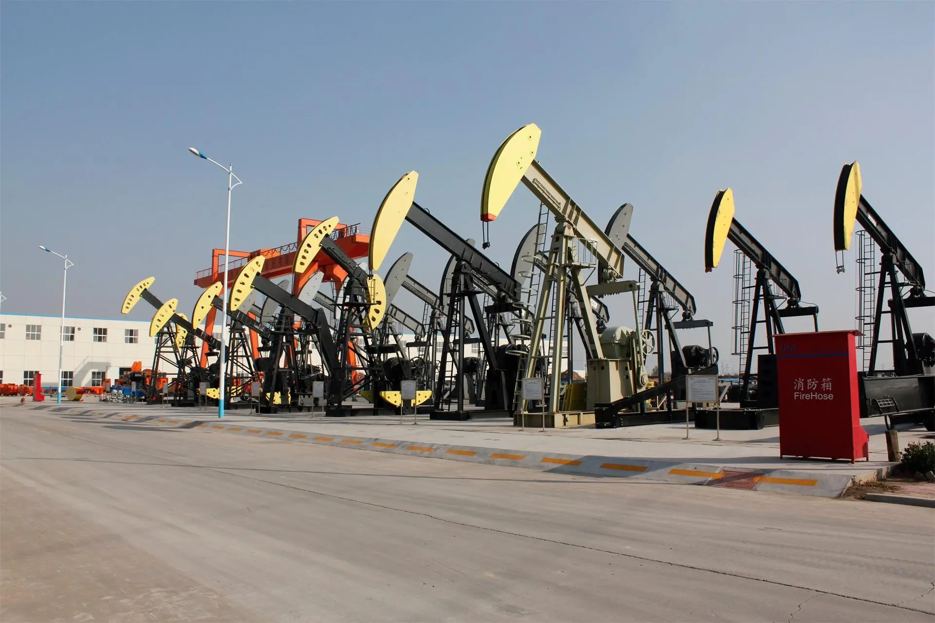
Pumping units are the machines that are employed to extract oil from the earth. These units come in a variety of shapes and sizes, each providing a unique advantage to the user. One such type of pumping unit is the conventional pumping unit with walking beams, balanced by cranks. This type of pumping unit is one of the most common and popular in use today.
Conventional pumping units are the most widely used kind of pump when it comes to producing oil. They consist of several parts, including a motor, a gearbox, a walking beam, cranks, and a pump jack. The motor powers the gearbox, which in turn turns the walking beam back and forth in a seesaw motion. The walking beam is connected on both sides to a crank, which is used to transfer energy from the motor to the pump jack. The pump jack is mounted on a wellhead and is used to lift and lower the pump rods. As the pump rods move up and down, the oil is drawn from the well.
The walking beam is one of the most important parts of the unit. It is a long, horizontal beam that is attached via a pivot to the base of the unit. At the opposite end of the beam is the cranks. The cranks convert the rotary motion of the motor into the back and forth motion of the walking beam. A series of mechanical linkages and gears transfer this motion to the pump jack, which drives the pump rods up and down. The pump rods are connected to a piston that is located near the bottom of the well. The reciprocal motion of the piston creates a suction that draws oil from the well.
One of the great advantages of conventional pumping units is their ability to operate in a wide range of conditions. They are capable of pumping large quantities of oil, making them ideal for heavy-duty applications. They are also highly reliable and can operate for extended periods without requiring maintenance. This makes them an ideal choice for remote installations where access to spare parts and technical expertise may be limited.
Another advantage of conventional pumping units is their low cost. They are relatively simple to manufacture, which means that they are less expensive than other types of pump. Also, their simple design means that they have fewer moving parts, which makes them easier to maintain. Finally, they are highly efficient, which means that they consume less energy than other types of pump.
In conclusion, conventional pumping units with walking beams, balanced by cranks, are one of the most common and popular types of pump in use today. They are capable of pumping large quantities of oil, are highly reliable, and can operate in diverse conditions. Furthermore, they are simple to manufacture, maintain, and operate, making them a cost-effective option for oil producers. If you are in the market for a pumping unit, then you should consider a conventional pumping unit with walking beams, balanced by cranks – a reliable and efficient option that has been proven over time.
Technical Performance & Characteristics
1.Modular and virtual manufacturing technologies are adopted in design, so that the structure of products is optimized and components are highly standardized, generalized and seriated.
2.Key structural elements are subject to finite element analysis to ensure stable performance and high reliability.
3.Reducers are driven by double-arc symmetrical split or involute herringbone wheels that are properly sealed and distinguished with low noise, smooth operation, reliable and durable service.
4.The entire machine features simple operation and maintenance and extended service life.
| NO. | Designation | Structure Capacity | Stroke | Strokes per minute | Motor Type | Reducer torque (103lb.in) | Total mass(t) | Unit size |
| (lbf×102) | (in) | L W H (m) | ||||||
| 1 | CW114-109-100HF | 109 | 100,86,67 | 5,7,9 | Y200L-8 | 114 | 11.1 | 7.0×1.9×6.6 |
| 2 | CW160-109-100HF | 109 | 100,86,67 | 5,7,9 | Y200L-8 | 160 | 12.1 | 7.0×2.0×6.6 |
| 3 | CW160-133-120F | 133 | 120,100,86 | 5,7,9 | YMJ180L-6 | 160 | 13.2 | 7.9×2.0×6.9 |
| 4 | CW160-173-120F | 173 | 120,100,86 | 6,8,10 | Y225S-8 | 160 | 15.5 | 8.1×2.0×6.9 |
| 5 | CW228-173-100F | 173 | 100,86,64 | 6,8,10 | Y225S-8 | 228 | 14.9 | 8.1×2.2×6.7 |
| 6 | CW228-173-120HF | 173 | 120,100,86 | 6,8,10 | Y200L1-6 | 228 | 14.9 | 7.6×2.1×6.9 |
| 7 | CW228-173-120F | 173 | 120,100,86 | 6,8,10 | Y225S-8 | 228 | 16.2 | 8.1×2.2×6.9 |
| 8 | CW160-200-74F | 200 | 74,64,48 | 6,9,12 | Y225M-8 | 160 | 14.7 | 8.1×2.2×6.7 |
| 9 | CW160-213-74F | 213 | 74,64,48 | 6,9,12 | GAS ENG. | 160 | 14.7 | 8.1×2.2×6.7 |
| 10 | CW228-213-100F | 213 | 100,86,74 | 6,8,10 | Y250M-8 | 228 | 20.1 | 8.1×2.1×6.7 |
| 11 | CW456-213-192HF | 213 | 192,168,144 | 4,6,8 | Y250M-8 | 456 | 25.8 | 11×2.52×9.5 |
| 12 | CW228-256-100F | 256 | 100,86,74 | 6,8,10 | Y250M-8 | 228 | 20.6 | 8.1×2.1×6.7 |
| 13 | CW228-256-100F | 256 | 100,86,74 | 6,8,10 | GAS ENG. | 228 | 20.6 | 8.1×2.1×6.7 |
| 14 | CW320-256-144F | 256 | 144,120,100 | 5,7,9 | Y280S-8 | 320 | 23.3 | 8.9×2.3×7.8 |
| 15 | CW456-256-144F | 256 | 144,120,100 | 5,7,9 | Y280S-8 | 456 | 25.5 | 8.9×2.3×7.8 |
| 16 | CW456-256-192HF | 256 | 192,168,144 | 4,6,8 | Y250M-8 | 456 | 26.3 | 11×2.52×9.5 |
| 17 | CW640-256-192HF | 256 | 192,168,144 | 4,6,8 | Y280M-8 | 640 | 29.2 | 10.9×2.52×9.8 |
| 18 | CW320-305-120F | 305 | 120,100,86 | 6,8,10 | Y280S-8 | 320 | 23.6 | 8.7×2.3×7.5 |
| 19 | CW320-305-120F | 305 | 120,100,86 | 6,8,10 | GAS ENG. | 320 | 23.6 | 8.7×2.3×7.5 |
| 20 | CW456-305-144F | 305 | 144,120,100 | 6,8,10 | Y280M-8 | 456 | 26.9 | 10×2.6×9.1 |
| 21 | CW456-305-168HF | 305 | 168,144,120 | 5,7,9 | Y280M-8 | 456 | 29.7 | 10.5×2.9×9.6 |
| 22 | CW640-305-168F | 305 | 168,144,120 | 5,7,9 | Y280M-8 | 640 | 32.6 | 10.8×2.9×9.1 |
| 23 | CW912-305-168F | 305 | 168,144,120 | 5,7,9 | Y315S-8 | 912 | 37.2 | 10.7×2.9×9.1 |
| 24 | CW640-305-192HF | 305 | 192,168,144 | 5,7,9 | Y280M-8 | 640 | 34.7 | 11.8×2.9×9.5 |
| 25 | CW640-365-192F | 365 | 192,168,144 | 4,6,8 | Y315S-8 | 640 | 34.9 | 11.3×2.9×9.6 |
| 26 | CW912-365-192F | 365 | 192,168,144 | 4,6,8 | Y315S-8 | 912 | 39 | 12.0×2.9×10.4 |
| 27 | CW912-365-216HF | 365 | 216,192,157 | 4,6,8 | YMJ280S-8 | 912 | 39.4 | 12.0×3.1×10.8 |
| No. | Designation | Structure Capacity | Stroke | Strokes per minute | Motor Type | Reducer torque (kN.m) | Total mass | Unit size |
| (kN) | (m) | (min-1) | (t) | L W H | ||||
| (m) | ||||||||
| 1 | CYJW5-2.5-13HF | 50 | 2.5, 2.1, 1.7 | 5,7,9 | Y200L-8 | 13 | 11.1 | 7.0×1.9×6.6 |
| 2 | CYJW5-2.5-18HF | 50 | 2.5, 2.1, 1.7 | 5,7,9 | Y200L-8 | 18 | 12.1 | 7.0×2.0×6.6 |
| 3 | CYJW6-3-18F | 60 | 3,2.5,2.1 | 5,7,9 | YMJ180L-6 | 18 | 13.2 | 7.9×2.0×6.9 |
| 4 | CYJW8-3-18F | 80 | 3,2.5,2.1 | 6,8,10 | Y225S-8 | 18 | 15.5 | 8.1×2.0×6.9 |
| 5 | CYJW8-2.5-26F | 80 | 2.5,2.1,1.6 | 6,8,10 | Y225S-8 | 26 | 14.9 | 8.1×2.2×6.7 |
| 6 | CYJW8-3-26HF | 80 | 3,2.5,2 | 6,8,10 | Y200L1-6 | 26 | 14.9 | 7.6×2.1×6.9 |
| 7 | CYJW8-3-26F | 80 | 3,2.5,2.1 | 6,8,10 | Y225S-8 | 26 | 16.2 | 8.1×2.2×6.9 |
| 8 | CYJW10-1.8-18F | 18 | 1.88,1.54,1.20 | 6,9,12 | Y225M-8 | 18 | 14.7 | 8.1×2.2×6.7 |
| 9 | CYJW10-2.5-26F | 100 | 2.5,2.1,1.6 | 6,8,10 | Y250M-8 | 26 | 20.1 | 8.1×2.1×6.7 |
| 10 | CYJW10-4.8-48HF | 100 | 4.8,4.2,3.6 | 4,6,8 | Y250M-8 | 48 | 25 | 10.5×2.52×9.5 |
| 11 | CYJW10-4.8-53HF | 100 | 4.8,4.2,3.6 | 4,6,8 | Y250M-8 | 53 | 25.8 | 11×2.52×9.5 |
| 12 | CYJW12-2.5-26F | 120 | 2.5,2.1,1.6 | 6,8,10 | Y250M-8 | 26 | 20.6 | 8.1×2.1×6.7 |
| 13 | CYJW12-3.6-37F | 120 | 3.6,3,2.4 | 5,7,9 | Y280S-8 | 37 | 23.3 | 8.9×2.3×7.8 |
| 14 | CYJW12-3.6-53F | 120 | 3.6,3,2.5 | 5,7,9 | Y280S-8 | 53 | 25.5 | 8.9×2.3×7.8 |
| 15 | CYJW12-4.8-53HF | 120 | 4.8,4.2,3.6 | 4,6,8 | Y250M-8 | 53 | 26.3 | 11×2.52×9.5 |
| 16 | CYJW12-4.8-73HF | 120 | 4.8,4.2,3.6 | 4,6,8 | Y280M-8 | 73 | 29.2 | 10.9×2.52×9.8 |
| 17 | CYJW14-3.0-37F | 140 | 3.0,2.5,2.0 | 6,8,10 | Y280S-8 | 37 | 23.6 | 8.7×2.3×7.5 |
| 18 | CYJW14-3.6-53F | 140 | 3.6,3,2.5 | 6,8,10 | Y280M-8 | 53 | 26.9 | 10×2.6×9.1 |
| 19 | CYJW14-4.2-53F | 140 | 4.2,3.6,3 | 5,7,9 | Y280M-8 | 53 | 29.7 | 10.5×2.9×9.6 |
| 20 | CYJW14-4.2-73F | 140 | 4.2,3.6,3 | 5,7,9 | Y280M-8 | 73 | 32.6 | 10.8×2.9×9.1 |
| 21 | CYJW14-4.2-105F | 140 | 4.2,3.6,3 | 5,7,9 | Y315S-8 | 105 | 37.2 | 10.7×2.9×9.1 |
| 22 | CYJW14-4.8-73HF | 140 | 4.8,4.2,3.6 | 5,7,9 | Y280M-8 | 73 | 34.7 | 11.8×2.9×9.5 |
| 23 | CYJW14-4.8-89HF | 140 | 4.8,4.2,3.6 | 4,6,8 | Y280M-8 | 89 | 33.5 | 10.8×2.9×9.5 |
| 24 | CYJW16-4.8-73F | 160 | 4.88,4.2,3.6 | 4,6,8 | Y315S-8 | 73 | 34.9 | 11.3×2.9×9.6 |
| 25 | CYJW16-4.8-89HF | 160 | 4.88,4.2,3.6 | 4,6,8 | Y315S-8 | 89 | 33.8 | 11.5×2.9×9.6 |
| 26 | CYJW16-4.8-105F | 160 | 4.88,4.2,3.6 | 4,6,8 | Y315S-8 | 105 | 39 | 12.0×2.9×10.4 |
| 27 | CYJW16-5.5-105HF | 160 | 5.5,4.7,4 | 4,6,8 | YMJ280S-8 | 105 | 39.4 | 12.0×3.1×10.8 |


