English ![]()

Tel:+0086 133 9331 8107
Mail:sales06@yppetro.com
Mail:sales06@yppetro.com
Professional oil drilling rig equipment sales.
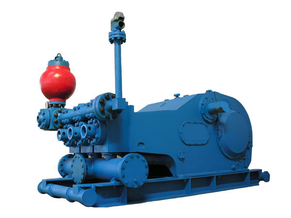
Rated Horsepower:1,600 HP
Model | F-500 | F-800 | F-1000 | F-1300 | F-1600 |
|---|---|---|---|---|---|
| House Power Rating KW/HP | 370KW(500HP) | 590/800 | 735/1000 | 956/1300 | 1176/1600 |
| Stroke Per Minute | 165 | 150 | 140 | 120 | |
| Size,Maximum Bore*Stroke | 170x191MM (6-3/4*5) | 170x229MM (6-3/4-X9") | 170x254MM (6-3/4W(T)) | 180x305MM(7'x12B) | |
| Gear Rating | 4.286:1 | 4.185:1 | 4.207:1 | 4.23:1 | |
| Suction Inlet | 8 | 10 | 12 | 12 | |
| Discharge Outlet | 4 | 5 | 5 | 5 | |
| Pinion Shaft Size | 139.7(5-1/2") | 177.8(7") | 196.9(7-3/4") | 215.9(8-1/2") | |
| Valve Pots | API-5" | API-6" | API-6" | API-7# | |
| Weight Kg | 13000/28660 | 18790/41425 | 23924/52743 | 24143/53226 | |
It ensures the smooth operation, and can meet the special requirements of users during shallow drilling and medium-deep drilling operations;
There are five models to choose from, input power from 597kW to 1640 kW;
The durable fluid end greatly improves the performance of the triplex mud pump.
Model | 8-P-80 | 9-P-100 | 10-P-130 | 12-P-160 | 14-P-220 |
|---|---|---|---|---|---|
| Suction inlet center height in(mm) | 10 3/4 (273) | 13 1/4(337) | 13 1/4(337) | 16 1/2(419) | 19 7/8(505) |
| Discharge port centcr height in(mm) | 35 1/4(895) | 38 1/4(972) | 39 1/4(997) | 45 1/4(1149) | 49 1/4(1251) |
| Substructure length in(mm) | 161 5/8(4105) | 176 1/4(4477) | 186 5/8(4740) | 209(5309) | 218 1/4(5544) |
| Pump body length in(mm) | 62 9/16(1589) | 67 1/8(1705) | 71 3/8(1813) | 75 5/8(1997) | 91 (2311) |
| Gear shaft length in(mm) | 93 7/8(2384) | 101 1/4(2572) | 107 1/4(2724) | 113 3/4(2889) | 125 3/4(3194) |
| Dymamic end height in(mm) | 60(1524) | 64(1626) | 67(1702) | 75(1905) | 84 1/4 (2139) |
| Fluid end height in(mm) | 51 7/8(1318) | 54 7/8(1394) | 5579/8(1419) | 62 15/16(1599) | 691/8(1756) |
| Max.inpul power HP(Kw) | 800(597) | 1000(746) | 1300(969) | 1600(1193) | 2200(1640) |
| Rated speed Spm | 160 | 150 | 140 | 120 | 105 |
| Max.ID of cylinder liner in(mm) | 6 1/4(158.8) | 6 3/4(171.5) | 6 3/4(171.5) | 7 1/4(184.2) | 9(228.6) |
| Stroke in(mm) | 8 1/2(215.9) | 9 1/4(235) | 10(254) | 12(304.8) | 14(355.6) |
| Test hydraulic pressure of hydraulic cylinder Psi(kg/cm ) | 10000(703) | 10000(703) | 10000(703) | 12(304.8) | 11250(791) |
| Gear ratio | 2.463 | 2.658 | 2.853 | 3.439 | 3.969 |
| Dia of suction pipe in | 8 | 8 | 8 | 10 | 10 |
| Dia of discharge pipe in | 4 | 5 | 5 | 6 | 6 |
| Speciflcation of Valves | MOD.6 | MOD.6 | MOD.6 | MOD.7 | MOD.8 |
| Weight(excl.belt wheel Ibs.kg) | 26970(12235) | 33200(15060) | 42550(19300) | 54700(24810) | 82000(37195) |
Dia of | Cutput | Pump Stroke / Revolution of Smail Gear oorresponding to its Displacement | |||||||||
| 50/230 | 120/552 | 200/920 | 300/1380 | 450/2070 | |||||||
| Inch(mm) | Gal/revoluti on (Lit/min) | Gal/min (Lit/min) | PSI (kg/cm²) | Gal/min (Lit/min) | PSI (kg/cm²) | Gal/min (Lit/min) | PSI (kg/cm²) | Gal/min (Lit/min) | PSI (kg/cm²) | Gal/min (Lit/min) | PSI (kg/cm²) |
| 2 1/2" (63.5) | .38(1.4) | 19(72) | 20,372(1438) | 46(174) | 20,165(1421) | 76(290) | 12,099(835) | 115(434) | 8,066(588) | 172(651) | 5,377(379) |
| 2 3/4" (69.9) | .48(1.8) | 23(87) | 16,836(1186) | 56(210) | 16,665(1174) | 93(350) | 9,999(705) | 139(526) | 6,666(470) | 208(788) | 4,444(313) |
| 3" (76.2) | .55(2.1) | 28(104) | 14,147(997) | 66(250) | 14,003(987) | 110(417) | 8,402(592) | 165(625) | 5,601(395) | 248(938) | 3,734(263) |
| 3 1/2" (88.9) | .75(2.8) | 37(142) | 10,394(732) | 90(341) | 10,288(725) | 150(568) | 6,173(435) | 225(851) | 4,115(290) | 337(1277) | 2,744(193) |
| 4" (101.6) | .98(3.7) | 49(185) | 7,958(561) | 118(445) | 7,877 (555) | 198(741) | 4,426(333) | 294(1112) | 3,151(222) | 441(1668) | 2,100(143) |
| 4 1/2" (114.3) | 1.24(4.7) | 62(235) | 6,288(443) | 149(563) | 6,224(439) | 248(938) | 3,734(263) | 372(1407) | 2,489(175) | 558(2111) | 1,680(117) |
| Input pow er Brakehorse pow cr(Kw) | 253(188) | 600(448) | 600(448) | 600(448) | 600(448) | ||||||
Type | Horizontal triplex reciprocating single acting piston pump |
|---|---|
| Trip(mm) | 180 |
| Cylinder diameter(mm) | 220 |
| Flow(L/min) | 800-3500 |
| Pressure(MPa) | 5-20 |
| Input power(KW) | 300 |
| Outline dimensions(mm) | 7000x2800x2400 |
| Mass(kg) | 12000 |
| Diesel engine model | WP12 |
| Diesel engine powe(KW) | 353 |
| Rated rotation speed(r/min) | 2100 |
| Item No. | Drawing Name | Part Number |
| 1 | F-1300 Assembly Drawing | AH36001-00 |
| 2 | F-1600 Assembly Drawing | AH37001-00 |
| 3 | F-1300 Crankshaft Assembly | AH36001-02.00 |
| 4 | F-1600 Crankshaft Assembly | AH37001-01.00 |
| 5 | F-1300 Pinion Shaft Assembly | AH36001-03.00 |
| 6 | F-1600 Pinion Shaft Assembly | AH37001-02.00 |
| 7 | F-1300/1600 Crosshead Assembly | AH36001-04.00 |
| 8 | F-1300/1600 Hydraulic End Assembly | AH36001-05.00 |
| 9 | F-1300/1600 Power End Lubrication Assembly | AH36001-06.00 |
| 10 | F-1300/1600 Spray Pump Assembly | AH36001-08.00 |
| 11 | F-1300/1600 Discharge Elbow Assembly | AH36001-22A.00 |
| 12 | F-1300/1600 Discharge Strainer Assembly | AH36001-23.00 |
| 13 | KB-75 Air Chamber | AH36001-18.00 |
| 14 | JA-3 Shear Relief Valve | AH36001-20A.00 |
| Item No. | Name | F-1300 Part Number | F-1600 Part Number |
| 1 | Frame Assembly | AH36001-01.00 | AH36001-01.00 |
| 2 | Crankshaft Assembly | AH36001-02.00 | AH37001-01.00 |
| 3 | Pinion Shaft Assembly | AH36001-03.00 | AH37001-02.00 |
| 4 | Crosshead Assembly | AH36001-04.00 | AH36001-04.00 |
| 5 | Hydraulic End Assembly | AH36001-05.00 | AH36001-05.00 |
| 6 | Power End Lubrication Assembly | AH36001-06.00 | AH36001-06.00 |
| 7 | Base Frame | AH36001-07.00 | AH36001-07.00 |
| 8 | Spray Pump Assembly | AH36001-08.00 | AH36001-08.00 |
| 9 | Sealing Washer | AH33001-09 | AH33001-09 |
| 10 | Air Filter | EF4-50 | EF4-50 |
| 11 | Cover Plate Assembly | AH360001-21C.00 | AH360001-21C.00 |
| 12 | Nameplate | AH36001-09 | AH37001-03 |
| 13 | 3T Manual Monorail Trolley | - | - |
| 14 | Lifting Frame | AH36001-11.00 | AH36001-11.00 |
| 15 | Cover Plate | AH36001-12.00 | AH36001-12.00 |
| 16 | Gasket | AH36001-13 | AH36001-13 |
| 17 | Indicator Plate | AH33001-17B | AH33001-17B |
| 18 | Oil Level Gauge Assembly | AH33001-18.00 | AH33001-18.00 |
| 19 | Drain Plug (Ⅲ) | AH33001-22.00 | AH33001-22.00 |
| 20 | Sealing Washer | AH36001-19 | AH36001-19 |
| 21 | Crosshead Hole Cover | AH36001-14 | AH37001-04 |
| 22 | Gasket | AH36001-15 | AH36001-15 |
| 23 | Rubber Strip (40×5×5800) | 40×5×5800 | 40×5×5800 |
| 24 | Discharge Elbow Assembly | AH36001-22A.00 | AH36001-22A.00 |
| 25 | Octagonal Gasket R.44-10 | GB/T 9128-2003 | GB/T 9128-2003 |
| 26 | Discharge Strainer Assembly | AH36001-23.00 | AH36001-23.00 |
| 27 | KB-75 Air Chamber | AH36001-18.00 | AH36001-18.00 |
| 28 | JA-3 Shear Pin Relief Valve | AH36001-20A.00 | AH36001-20A.00 |
| 29 | Seismic Pressure Gauge 60MPa 8700psi | YK-150F(Φ215) | YK-150F(Φ215) |
| Item No. | Name | F-1300 Part Number | F-1600 Part Number |
| 1 | Main Bearing End Cover | AH36001-02.01.00 | AH36001-02.01.00 |
| 2 | Main Bearing Sleeve (Right) | AH36001-02.02 | AH37001-01.01 |
| 3 | Connecting Rod | AH36001-02.06 | AH37001-01.03 |
| 4 | Positioning Ring (I) | AH36001-02.07 | AH36001-02.07 |
| 5 | Hollow Crankshaft | AH36001-02.08.00 | AH36001-02.08.00 |
| 6 | Positioning Ring (II) | AH36001-02.09 | AH36001-02.09 |
| 7 | Large Gear Ring | AH36001-02.10.00 | AH37001-01.04.00 |
| 8 | Bolt 1 1/2-8UNx10 | T50-2034 | T50-2034 |
| 9 | Nut 1 1/2-8UN | T51-2001 | T51-2001 |
| 10 | Main Bearing Sleeve (Left) | AH36001-02.12 | AH37001-01.05 |
| 11 | Main Bearing Bolt | AH36001-02.15 | AH36001-02.15 |
| 12 | Eccentric Wheel Bearing | AH36001-02.17 | AH37001-01.07 |
| 13 | Main Bearing | AH36001-02.18 | AH37001-01.08 |
| 14 | Crankshaft Counterweight | AH36001-02.19 | AH36001-02.19 |
| Item No. | Name | F-1300 Part Number | F-1600 Part Number |
| 1 | Key 2"×2"×9-1/2" | AH36001-03.01 | AH36001-03.01 |
| 2 | Pinion Shaft | AH36001-03.02 | AH37001-02.01 |
| 3 | Wear-Resistant Sleeve | AH36001-03.03 | AH36001-03.03 |
| 4 | End Cover | AH36001-03.04 | AH36001-03.04 |
| 5 | Bearing Sleeve | AH36001-03.07 | AH36001-03.07 |
| 6 | Pump Flange Plate | AH36001-03.13 | AH36001-03.13 |
| 7 | Bolt 1/2-13UNCx1 3/8 | T50-1019 | T50-1019 |
| 8 | Oil Seal 9.125"×10.375"×0.625" | AH36001-03.11 | AH36001-03.11 |
| 9 | Bearing 4G32844H | AH36001-03.12 | AH36001-03.12 |
| 10 | Oil Collection Box | AH36001-03.10.00 | AH36001-03.10.00 |
| 11 | Retaining Ring | AH36001-03.08 | AH36001-03.08 |
| 12 | Bolt 7/8-9UNCx2 | T50-1027 | T50-1027 |
| 13 | Bolt 5/8-11UNCx1 3/4 | T50-1008 | T50-1008 |
| Item No. | Name | Part Number |
| 1 | Crosshead | AH36001-04.01 |
| 2 | Upper Guide Plate | AH36001-04.02 |
| 3 | Gasket Set | AH33001-04.17.00 |
| 4 | Oil Seal Ring | AH36001-04.05 |
| 5 | Double-Lip Oil Seal 5"×6.25"×0.625" | AH36001-04.06 |
| 6 | Locking Spring | AH36001-04.07 |
| 7 | Mud Guard | AH36001-04.08 |
| 8 | Intermediate Tie Rod | AH36001-04.09 |
| 9 | Crosshead Pin | AH36001-04.10 |
| 10 | Lower Guide Plate | AH36001-04.12 |
| 11 | Crosshead Pin Baffle Plate | AH36001-04.13 |
| 12 | Crosshead Bearing 254941QU | AH36001-04.14 |
| 13 | Pipe Fitting Z3/8×2 | AH33001-04.05 |
| 14 | Bolt 1-8UNC×2-1/4 | T50-2018K |
| 15 | Bolt 1-8UNC×2-1/2 | T50-2019K |
| 16 | Fixing Plate | AH36001-04.15 |
| 17 | Screw 1-8UNC×2-1/2 | AH36001-04.16 |
| 18 | O-Ring φ125×7 | GB/T 3452.1-2005 |
| 19 | O-Ring φ160×7 | GB/T 3452.1-2005 |
| 20 | O-Ring φ190×3.55 | GB/T 3452.1-2005 |
| 21 | Bolt 3/8-16UNC×1 | T50-1021 |
| 22 | Bolt 3/4-10UNC×2-1/2 | T50-3010 |
| Item No. | Name | Part Number |
| 1 | Liquid Cylinder Assembly | AH36001-05.01.00 |
| 2 | Cylinder Head Flange | AH36001-05.02 |
| 3 | Cylinder Head | AH36001-05.03 |
| 4 | Plug Plate Assembly | AH36001-05.04.00 |
| 5 | Valve Stem Guide (Lower) | AH36001-05.05.00 |
| 6 | Cylinder Head Plug | AH36001-05.06.00 |
| 7 | Positioning Disk | AH36001-05.07 |
| 8 | Cylinder Head Seal Ring | AH36001-05.08 |
| 9 | Discharge Pipe | AH36001-05.09 |
| 10 | Valve Spring | AH33001-05.16A |
| 11 | Valve Assembly | AH36001-05.24.00 |
| 12 | Valve Cover Seal Ring | AH36001-05.10 |
| 13 | Valve Cover | AH36001-05.11 |
| 14 | Cylinder Liner Seal Ring | AH36001-05.12 |
| 15 | Wear-Resistant Disk | AH36001-05.13 |
| 16 | Cylinder Liner Flange | AH36001-05.14 |
| 17 | Cylinder Liner Gland | AH36001-05.15.00 |
| 18 | Piston Rod | AH36002-05.02 |
| 19 | Cylinder Liner Lock Ring | AH36001-05.18 |
| 20 | Bimetallic Cylinder Liner | AH36002-05.03.00 |
| 21 | Clamp Assembly | AH36001-05.19.00 |
| 22 | Cylinder Liner End Cover | AH36001-05.20 |
| 23 | Piston | AH36002-05.04.00 |
| 24 | Suction Pipe | AH36001-05.22.00 |
| 25 | Gasket Set | AH36001-05.23.00 |
| 26 | Valve Stem Guide (Upper) | AH33001-05.12 |
| 27 | Double-Ended Bolt 1 1/2-8UN×10 1/2 | T50-7002 |
| 28 | Baffle Plate | AH33001-05.14 |
| 29 | Bolt 3/8-16UNC×3/4 | AH36001-05.27 |
| 30 | Piston Seal Ring | AH33001-05.20A |
| 31 | Lock Nut M39×3 | 2112.80.01A.00 |
| 32 | Suction Air Chamber | AH33001-05.35A.00 |
| 33 | Double-Ended Stud 1 1/2-8UN | AH36001-05.28 |
| 34 | Nut 1 1/2-8UN | T51-2001 |
| 35 | O-Ring φ95×5.3 | GB/T 3452.1-2005 |
| 36 | O-Ring φ200×7 | GB/T 3452.1-2005 |
| 37 | Bolt 7/8-9UNC×2 | T50-1027 |
| 38 | O-Ring φ185×7 | GB/T 3452.1-2005 |
| 39 | O-Ring φ345×7 | GB/T 3452.1-2005 |
| 40 | Nut 1-8UNC | T51-1003 |
| 41 | Bolt 1-8UNC×3 1/2 | T50-1023 |
| 42 | Fitting NPT3/8-M22×1.5 | AH35001-04.16A |
| 43 | Crimped Hose Assembly C-13×1W-800 JB1887-77 | C-13×1W-800 JB1887-77 |
| 44 | Fitting NPT1/2-M22×1.5 | AH36001-05.30 |
| 45 | Right-Angle Fitting NPT1-NPT1/2 | AH36001-05.31 |
| Item No. | Name | Part Number |
| 1 | Oil Pump Gear Assembly | AH36001-06.01.00 |
| 2 | Fitting Seat (Ⅱ) | AH33001-06.40 |
| 3 | Oil Filter Assembly | AH36001-06A.33.00 |
| 4 | Fitting Seat (Ⅰ) | AH33001-06A.11 |
| 5 | Support Bracket | AH36001-06.02.00 |
| 6 | Pressure Relief Valve | YYFJ-L20 |
| 7 | Oil Nozzle | AH36001-06.03 |
| 8 | 2S Gear Oil Pump | - |
| 9 | Dual-Scale Pressure Gauge (0~1.6MPa, 230psi M14×1.5) | Y60-Z |
| Item No. | Name | Part Number |
| 1 | Oil Seal 9.125"×10.375"×0.625" | AH36001-03.11 |
| 2 | Oil Seal Ring | AH36001-04.05 |
| 3 | Double-Lip Oil Seal 5"×6.25"×0.625" | AH36001-04.06 |
| 4 | Cylinder Head Seal Ring | AH36001-05.08 |
| 5 | Valve Cover Seal Ring | AH36001-05.10 |
| 6 | Cylinder Liner Seal Ring | AH36001-05.12 |
| 7 | Rubber Sheet 6 3/4" | AH36002-05.21.02.02.00 |
| 8 | Valve Rubber Sheet | AH36001-05.24.03 |
| 9 | Air Bag Assembly | AH36001-18.01.00 |
| 10 | O-Ring φ41.2×3.55NBR | GB/T 3452.1 |
| 11 | Air Chamber Bladder | AH33001-05.35A.02 |
| 12 | Sealing Washer | AH33001-09 |
| 13 | Retaining Ring φ200×φ185×2.5 | AH33001-31.09.04 |
| 14 | O-Ring φ200×8.6 | AH33001-31.09.05 |
| 15 | Retaining Ring φ80×φ70×2 | AH33001-31.09.06 |
| 16 | O-Ring φ80×5.7 | AH33001-31.09.07 |
| 17 | Piston Assembly | AH33003-03.00 |
| 18 | Buffer Pad | AH33003-06 |
| 19 | Shear Pin | AH33003-11 |
| 20 | O-Ring φ95×5.3NBR | GB/T 3452.1 |
| 21 | O-Ring φ125×7NBR | GB/T 3452.1 |
| 22 | O-Ring φ160×7NBR | GB/T 3452.1 |
| 23 | O-Ring φ185×7NBR | GB/T 3452.1 |
| 24 | O-Ring φ190×3.55NBR | GB/T 3452.1 |
| 25 | O-Ring φ200×7NBR | GB/T 3452.1 |
| 26 | O-Ring φ345×7NBR | GB/T 3452.1 |
| 27 | Octagonal Gasket R.39-10 | GB/T 9128 |
| 28 | Octagonal Gasket R.44-10 | GB/T 9128 |
| 29 | Octagonal Gasket R.27-10 | GB/T 9128 |
| 30 | Octagonal Gasket R.24-10 | GB/T 9128 |
| 31 | Cylinder Liner Hoisting Tool | AH36001-17.01.00 |
| 32 | Cylinder Head Rod | AH36001-17.02A |
| 33 | 24" Extension Rod | AH36001-17.03 |
| 34 | Sleeve 2 3/8" | AH36001-17.04 |
| 35 | Socket 2" | AH36001-17.05 |
| 36 | 19-5/8 Extension Rod | AH36001-17.06 |
| 37 | Socket 3 5/8" | AH36001-17.07 |
| 38 | Socket 1 1/2" | AH36001-17.08 |
| 39 | Adapter Fitting | AH36001-17.09 |
| 40 | 8" Extension Rod | AH36001-17.11 |
| 41 | Fitting 1" | AH36001-17.12 |
| 42 | Long Socket | AH36001-17.13.00 |
| 43 | Hydraulic Valve Puller | AH36001-17.15.00 |
| 44 | Short Screw Rod | AH36001-17.19 |
| 45 | Piston Nut Remover Stand | AH36001-17.21.00 |
| 46 | Plug Plate Extractor | AH36001-17.22.00 |
| 47 | Bolt 1-8UNC-2A×220 | AH36001-17.23 |
| 48 | Bolt 3/4-10UNC-2A×140 | AH36001-17.24 |
| 49 | Adapter Connector | AH36001-17.25 |
| 50 | Packing Guide Sleeve | AH36001-17.26 |
| 51 | Air Chamber Inflation Hose Assembly | 2112ZJ-02 |
| 52 | Manual Oil Pump (63MPa, 2m Hose, M16×1.5 Fitting) | SZB-2 |
| 53 | Chain Block HS1/2 Z Class | Standard Part |
| 54 | Allen Wrench 5/8" | Standard Part |
| 55 | Impact Spanner S60 | GB/T 4392 |